- PFXFP5600TPD
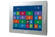
- PFXFP5600TPD
- 12.1"
Documentation
Support
Design Tools
Certifications
Functional Specifications
| Display Type | TFT Color LCD
|
|---|---|
| Display Size | 12-inch*1
|
| Resolution | 1,024 x 768 pixels (XGA)
|
| Effective Display Area | W245.76 x H184.32 mm (W9.68 x H7.26 in.)
|
| Display Colors | 16 million colors
|
| Backlight | White LED (Not user replaceable. When replacement is required, contact your local distributor.)
|
| Brightness Control | 0 to 100 (Adjusted with the launcher)
|
| Touch Panel Type | Resistive film (analog, multi-touch)
|
| Touch Panel Service Life | 1 million times or more
|
| Touch Panel Interface | USB 2.0 (Type B) *1*2
|
| USB (TYPE-A) | Front side: USB 2.0 (Type A) x 1
|
| USB (mini-B) | USB 2.0 (Type B) x 1
|
| Video | DVI-D input
|
General Specifications
| International Safety Standards |  |
|---|---|
| Rated Input Voltage | 12 to 24Vdc
|
| Input Voltage Limits | 10.8 to 28.8Vdc
|
| Power Consumption | Backlight ON: 100% (Power is supplied to external devices) - 30 A or less21W or less
Backlight ON: 100% (Power is not supplied to external devices) -18W or less Backlight adjusted: 20% (Power is not supplied to external devices) - 11W or less Backlight OFF (Power is not supplied to external devices) - 8W or less |
| In-Rush Current | 30 A or less
|
| Voltage Endurance | 1,000 Vac, 20 mA for 1 minute (between charging and FG terminals)
|
| Insulation Resistance | 500 Vdc, 10 MΩ or more (between charging and FG terminals)
|
| Surrounding Air Temperature | 0 to 60 ℃ (32 to 140 ℉)
|
| Storage Temperature | -20 to 60 ℃ (-4 to 140 ℉)
|
| Storage Humidity | 10% to 90% RH (non-condensing, wet bulb temperature 39 ℃
[102.2 ℉] or less) |
| Dust | 0.1mg/m3 (10-7 oz/ft3) or less (non-conductive levels)
|
| Pollution Degree | For use in Pollution Degree 2 environment
|
| Atmosphere | 800 to 1,114hPa (2,000 m [6,561 ft] or lower)
|
| Vibration Resistance | IEC/EN 61131-2 compliant
5 to 9 Hz single amplitude 3.5 mm (0.14 in) 9 to 150 Hz fixed acceleration: 9.8 m/s2 X, Y, Z directions for 10 cycles (approx. 100 min.) |
| Noise Immunity | Noise voltage: 1,000 Vp-p, Pulse duration: 1 μs. Rise time: 1 ns (via noise simulator)
|
| Electrostatic Discharge Immunity | Contact discharge method: 6 kV (IEC/EN 61000-4-2 Level 3)
|
| Grounding | Functional grounding: Grounding resistance of 100Ω, 2 mm2 (AWG 14) or thicker wire, or your country’s applicable standard (same for FG and SG terminals).
|
| Structure | When using a factory-installed front USB cover: IP65F, IP67F, Type 1
When using a front USB cover as an option: IP66F, IP67F, Type 1, Type 4X (Indoor Use Only)/13 NOTE: The option is a front USB cover with screw manufactured by Pro-face (Model Number PFXZCDCVUS1).*3 |
| Cooling Method | Natural air circulation
|
| Weight Approx. | 5.2 kg (11.5 lb) or less
|
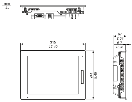
| External Dimensions | W315 x H241 x D67 mm (W12.4 x H9.49 x D2.64 in.)*4
|
| Panel Cut Dimensions | W301.5 x H227.5 mm (W11.87 x H8.96 in.) *2
Panel thickness area: 1.6 to 5 mm (0.06 to 0.2 in) *3 |
3*1 The front face of this product, installed in a solid panel, has been tested using conditions equivalent to the standards shown in the specification. Even though this product's level of resistance is equivalent to these standards, oils that should have no effect on this product can possibly harm this product. This can occur in areas where either vaporized oils are present, or where low viscosity cutting oils are allowed to adhere to this product for long periods of time. If this product's front face protection sheet peels off, these conditions can lead to the ingress of oil into this product and separate protection measures are suggested. Also, if non-approved oils are present, they may cause deformation or corrosion of the front panel's plastic cover. Therefore, prior to installing this product, be sure to confirm the type of conditions that will be present in this product's operating environment. If the installation gasket is used for a long period of time, or if this product and its gasket are removed from the panel, the original level of protection cannot be kept. To maintain the original protection level, be sure to replace the installation gasket regularly. For dimensional tolerance, everything +1/-0 mm (+0.04/-0 in.) and R in angle are below R3 (R0.12 in).
4*2 For dimensional tolerance, everything +1/-0 mm (+0.04/-0 in.) and R in angle are below R3 (R0.12 in). *3 Even if the installation wall thickness is within the recommended range for the panel cut dimensions, depending on wall's material, size, and installation location of this product and other devices, the installation wall could warp. To prevent warping, the installation surface may need to be strengthened.
External Dimensions
Panel Cut-Out
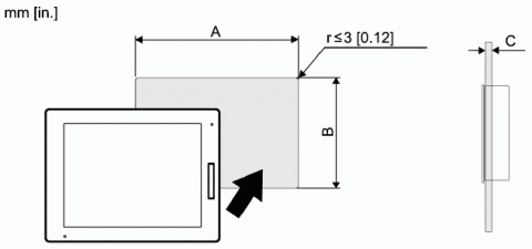
| A | B | C |
|---|---|---|
| 301.5 mm (+1/-0 mm) (11.87 in. [+0.04/-0 in.]) |
227.5 mm (+1/-0 mm) (8.96 in. [+0.04/-0 in.]) |
1.6 to 5 mm (0.06 to 0.2 in.) |