- GP-4601T (Rear Mount Model)

- PFXGP4601TADR
- PFXGP4601TADRF0C
- 12.1"
Documentation
Support
Quick Information
Design Tools
Software
Certifications
Functional Specifications
| Display Type | TFT Color LCD
|
|---|---|
| Display Size | 12.1"
|
| Resolution | 800 x 600 pixels (SVGA)
|
| Effective Display Area | W246.0 x H184.5 mm [W9.69 x H7.26 in.]
|
| Display Colors | 65,536 Colors (No blink)/16,384 Colors (Blink)
|
| Backlight | White LED (User nonreplaceable parts. When replacement is required, contact your local distributor.)
|
| Brightness Control | 16 Levels (Adjusted with the touch panel or the software)
|
| Backlight Service Life | 50,000 hrs. or more (continuous operation at 25°C [77 °F] before backlight brightness decreases to 50%)
|
| Language Fonts | Japanese: 6,962 (JIS Standards 1 & 2) (including 607 non-kanji characters) ANK: 158 (Korean fonts, Simplified Chinese and Traditional Chinese fonts are downloadable.)
|
| Character Sizes | Standard font: 8 x 8, 8 x 16, 16 x 16 and 32 x 32 pixel fonts, Stroke font: 6 to 127 pixel fonts, Image font: 8 to 72 pixel fonts
|
| Font Sizes | Standard font: Width can be expanded up to 8 times. Height can be expanded up to 8 times.*1
|
| 8 x 16 dots | 100 char. x 37 rows
|
| 16 x 16 dots | 50 char. x 37 rows
|
| 32 x 32 dots | 25 char. x 18 rows
|
| 8 x 8 dots | 100 char. x 75 rows
|
| Program Area | FLASH EPROM 132 KB (Equivalent to 15,000 steps)*2
|
| Variable Area | SRAM 64 KB (Replaceable Lithium battery for backup memory)
|
| Application Memory | FLASH EPROM 32 MB (including a logic program area)
|
| Data Backup | SRAM 320 KB (Replaceable Lithium battery for backup memory)
|
| Clock Accuracy | ±65 sec/month (deviation at room temperature and power is OFF)*3
|
| Touch Panel Type | Resistive Film (analog)
|
| Touch Panel Resolution | 1,024 x 1,024
|
| Touch Panel Service Life | 1,000,000 times or more
|
| Serial (COM1) | RS-232C Asynchronous Transmission Data Length: 7 or 8 bits, Parity: none, Odd or Even, Stop Bit: 1 or 2 bits, Data Transmission Speed: 2,400 bps to 115.2 kbps, Connector: D-Sub9 (plug)
|
| Serial (COM2) | RS-422/485 Asynchronous Transmission Data Length: 7 or 8 bits, Parity: none, Odd or Even Stop Bit: 1 or 2 bits, Data Transmission Speed: 2,400 bps to 115.2 kbps, 187.5kbps (MPI) Connector: D-Sub9 (plug)
|
| Ethernet (LAN) | IEEE802.3i/IEEE802.3u, 10BASE-T/100BASE-TX Connector: Modular jack (RJ-45) x 1
|
| USB (TYPE-A) | Conforms to USB2.0 (TYPE-A) x 1, Power Supply Voltage: DC 5 V ±5 %, Output Current: 500 mA or less, Communication Distance: 5 m [16.4ft.] or less
|
| USB (mini-B) | Conforms to USB2.0 (mini-B) x 1, Communication Distance: 5 m [16.4ft.] or less
|
| SD Card | SD Card Slot x 1
|
1Other font sizes can be set up with the Editor software.
2Up to 60,000 steps can be converted in software. However, this reduces application memory capacity (for screen data) by 1 MB.
3Depending on the operating temperature and age of unit, the clock can deviate from -380 to +90 sec/month. For systems where this level of deviation is a problem, the user should monitor and make adjustments when required.
General Specifications
| International Safety Standards |   |
|---|---|
| Rated Input Voltage | DC 24V
|
| Input Voltage Limits | DC 19.2 to 28.8V
|
| Allowable Voltage Drop | 10 ms or less
|
| Power Consumption | 17 W or less
|
| In-Rush Current | 30 A or less
|
| Voltage Endurance | AC 1,000 V 20 mA for 1 min (between charging and FG terminals)
|
| Insulation Resistance | DC 500 V, 10 MΩ or more (between charging and FG terminals)
|
| Surrounding Air Temperature | 0 to 55 °C (32 to 131 °F)
|
| Storage Temperature | -20 to 60 °C (-4 to 140 °F)
|
| Ambient Humidity | 10 to 90 % RH (Wet bulb temperature: 39 °C [102.2 °F] or less - no condensation.)
|
| Storage Humidity | 10 to 90 % RH (Wet bulb temperature: 39 °C [102.2 °F] or less - no condensation.)
|
| Dust | 0.1 mg/m³ (10⁻⁷ oz/ft³) or less (non-conductive levels)
|
| Pollution Degree | For use in Pollution Degree 2 environment
|
| Atmosphere | Free of corrosive gases
|
| Air Pressure (altitude range) | 800 to 1,114 hPa (2,000 m [6,561ft.] above sea level or less)
|
| Vibration Resistance | IEC/EN61131-2 compliant, 5 to 9 Hz Single amplitude 3.5 mm [0.14 in.], 9 to 150 Hz Fixed acceleration: 9.8 m/s², X, Y, Z directions for 10 cycles (approx. 100 min)
|
| Concussion Resistance | IEC/EN61131-2 compliant 147 m/s², X, Y, Z directions for 3 times
|
| Noise Immunity | Noise Voltage: 1,000 Vp-p, Pulse Duration: 1 µs, Rise Time: 1 ns (via noise simulator)
|
| Electrostatic Discharge Immunity | Contact Discharge Method: 6 kV (IEC/EN61000-4-2 Level 3)
|
| Grounding | Functional grounding: Grounding resistance of 100Ω, 2mm² (AWG 14) or thicker wire, or your country's applicable standard. (Same for FG and SG terminals)
|
| Structure | IP20*4
|
| Cooling Method | Natural air circulation
|
| Weight Approx. | 2.8 kg [6.2 lb] or less (including the installation fasteners)
|
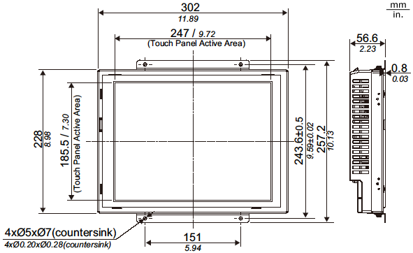
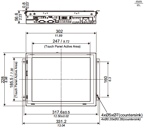
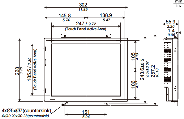
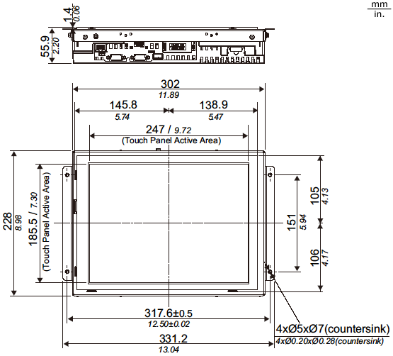
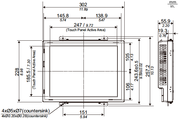
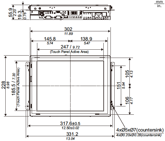
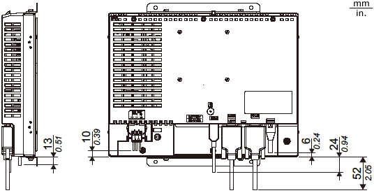
| External Dimensions | W302 x H228 x D56.6 mm [W11.89 x H8.98 x D2.23 in.]
|
| Panel Cut Dimensions | Standard Mount: W249.6 x H188.1 mm [W9.83 x H7.41 in.]
Flat Mount: W289.4 x H214.4 mm [W11.39 x H8.44 in.]*5 |
4Protection structure equivalent to IP65F can be expected if you affix the Overlay (sold separately) on the screen of the GP unit and the surroundings. Pro-face does not guarantee the protective structure. Consider the the protective structure in combination with a panel or a resin plate within your quality assurance range. For details, please refer to GP4000 Series Hardware Manual.
5As for dimensional tolerance everything +0.5/-0 mm (+0.02/-0 in.) and R in angle are below R1 (R0.04in.).