- GP-4501T (Rear Mount Model)
- PFXGP4501TADR
- PFXGP4501TADRFOC
- 10.4"
Documentation
Support
Quick Information
Design Tools
Software
Certifications
Functional Specifications
| Display Type | TFT Color LCD
|
|---|---|
| Display Size | 10.4"
|
| Resolution | 640 x 480 pixels (VGA)
|
| Effective Display Area | W211.2 x H158.4 mm [W8.31 x H6.24 in.]
|
| Display Colors | 65,536 Colors (No blink)/16,384 Colors (Blink)
|
| Backlight | White LED (User nonreplaceable parts. When replacement is required, contact your local distributor.)
|
| Brightness Control | 16 Levels (Adjusted with the touch panel or the software)
|
| Backlight Service Life | 50,000 hrs. or more (continuous operation at 25°C [77 °F] before backlight brightness decreases to 50%)
|
| Language Fonts | Japanese: 6,962 (JIS Standards 1 & 2) (including 607 non-kanji characters) ANK: 158 (Korean fonts, Simplified Chinese and Traditional Chinese fonts are downloadable.)
|
| Character Sizes | Standard font: 8 x 8, 8 x 16, 16 x 16 and 32 x 32 pixel fonts, Stroke font: 6 to 127 pixel fonts, Image font: 8 to 72 pixel fonts
|
| Font Sizes | Standard font: Width can be expanded up to 8 times. Height can be expanded up to 8 times.*1
|
| 8 x 16 dots | 80 char. x 30 rows
|
| 16 x 16 dots | 40 char. x 30 rows
|
| 32 x 32 dots | 20 char. x 15 rows
|
| 8 x 8 dots | 80 char. x 60 rows
|
| Program Area | FLASH EPROM 132 KB (Equivalent to 15,000 steps)*2
|
| Variable Area | SRAM 64 KB (Replaceable Lithium battery for backup memory)
|
| Application Memory | FLASH EPROM 32 MB (including a logic program area)
|
| Data Backup | SRAM 320 KB (Replaceable Lithium battery for backup memory)
|
| Clock Accuracy | ±65 sec/month (deviation at room temperature and power is OFF)*3
|
| Touch Panel Type | Resistive Film (analog)
|
| Touch Panel Resolution | 1,024 x 1,024
|
| Touch Panel Service Life | 1,000,000 times or more
|
| Serial (COM1) | RS-232C Asynchronous Transmission Data Length: 7 or 8 bits, Parity: none, Odd or Even, Stop Bit: 1 or 2 bits, Data Transmission Speed: 2,400 bps to 115.2 kbps, Connector: D-Sub9 (plug)
|
| Serial (COM2) | RS-422/485 Asynchronous Transmission Data Length: 7 or 8 bits, Parity: none, Odd or Even Stop Bit: 1 or 2 bits, Data Transmission Speed: 2,400 bps to 115.2 kbps, 187.5kbps (MPI) Connector: D-Sub9 (plug)
|
| Ethernet (LAN) | IEEE802.3i/IEEE802.3u, 10BASE-T/100BASE-TX Connector: Modular jack (RJ-45) x 1
|
| USB (TYPE-A) | Conforms to USB2.0 (TYPE-A) x 1, Power Supply Voltage: DC 5 V ±5 %, Output Current: 500 mA or less, Communication Distance: 5 m [16.4ft.] or less
|
| USB (mini-B) | Conforms to USB2.0 (mini-B) x 1, Communication Distance: 5 m [16.4ft.] or less
|
| SD Card | SD Card Slot x 1
|
1Other font sizes can be set up with the Editor software.
2Up to 60,000 steps can be converted in software. However, this reduces application memory capacity (for screen data) by 1 MB.
3Depending on the operating temperature and age of unit, the clock can deviate from -380 to +90 sec/month. For systems where this level of deviation is a problem, the user should monitor and make adjustments when required.
General Specifications
| International Safety Standards |   |
|---|---|
| Rated Input Voltage | DC 24V
|
| Input Voltage Limits | DC 19.2 to 28.8V
|
| Allowable Voltage Drop | 10 ms or less
|
| Power Consumption | 17 W or less
|
| In-Rush Current | 30 A or less
|
| Voltage Endurance | AC 1,000 V 20 mA for 1 min (between charging and FG terminals)
|
| Insulation Resistance | DC 500 V, 10 MΩ or more (between charging and FG terminals)
|
| Surrounding Air Temperature | 0 to 55 °C (32 to 131 °F)
|
| Storage Temperature | -20 to 60 °C (-4 to 140 °F)
|
| Ambient Humidity | 10 to 90 % RH (Wet bulb temperature: 39 °C [102.2 °F] or less - no condensation.)
|
| Storage Humidity | 10 to 90 % RH (Wet bulb temperature: 39 °C [102.2 °F] or less - no condensation.)
|
| Dust | 0.1 mg/m³ (10⁻⁷ oz/ft³) or less (non-conductive levels)
|
| Pollution Degree | For use in Pollution Degree 2 environment
|
| Atmosphere | Free of corrosive gases
|
| Vibration Resistance | IEC/EN61131-2 compliant, 5 to 9 Hz Single amplitude 3.5 mm [0.14 in.], 9 to 150 Hz Fixed acceleration: 9.8 m/s², X, Y, Z directions for 10 cycles (approx. 100 min)
|
| Concussion Resistance | IEC/EN61131-2 compliant 147 m/s², X, Y, Z directions for 3 times
|
| Noise Immunity | Noise Voltage: 1,000 Vp-p, Pulse Duration: 1 µs, Rise Time: 1 ns (via noise simulator)
|
| Electrostatic Discharge Immunity | Contact Discharge Method: 6 kV (IEC/EN61000-4-2 Level 3)
|
| Grounding | Functional grounding: Grounding resistance of 100Ω, 2mm² (AWG 14) or thicker wire, or your country's applicable standard. (Same for FG and SG terminals)
|
| Structure | IP20*5
|
| Cooling Method | Natural air circulation
|
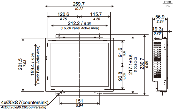
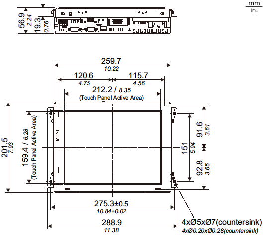
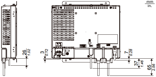
| Weight Approx. | 2.3 kg [5.1 lb] or less (including the installation fasteners)
|
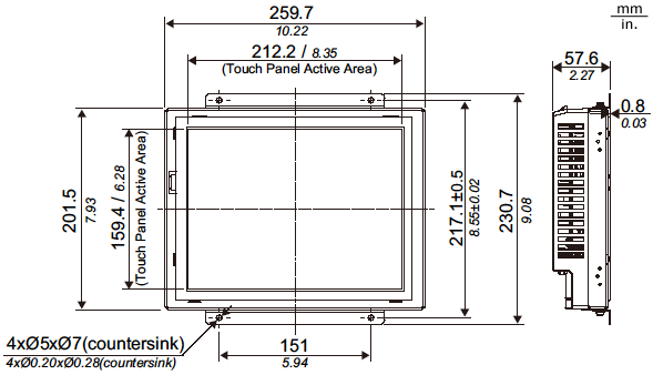
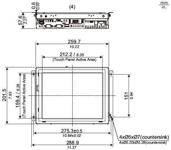
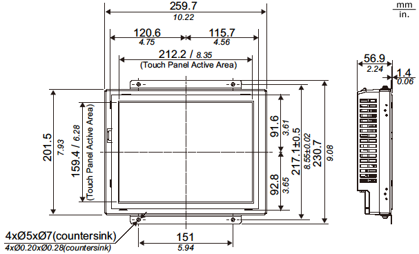
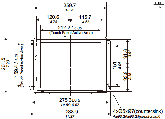
| External Dimensions | W259.7 x H201.5 x D57.6 mm [W10.22 x H7.93 x D2.27 in.]
|
| Panel Cut Dimensions | Standard Mount: W214.8 x H162 mm [W8.46 x H6.38 in.]
Flat Mount: W241 x H188 mm [W9.49 x H7.4 in.]*6 |
4800 to 1,114 hPa (2,000 m [6,561ft.] above sea level or less)
5Protection structure equivalent to IP65F can be expected if you affix the Overlay (sold separately) on the screen of the GP unit and the surroundings. Pro-face does not guarantee the protective structure. Consider the the protective structure in combination with a panel or a resin plate within your quality assurance range. For details, please refer to GP4000 Series Hardware Manual.
6As for dimensional tolerance everything +0.5/-0 mm (+0.02/-0 in.) and R in angle are below R1 (R0.04in.).