Manual | PFXSP800WCD Datasheet | PFXSP5B41 Datasheet | Technical Resources | Software | Certifications | SP5000 Flyer
Display Specifications
| Display Type | TFT Color LCD | |
|---|---|---|
| Display Size* | 18.5” | |
| Resolution | 1366 x 768 pixels (FWXGA) | |
| Auto Scaling | Yes | |
| Effective Display Area | W409.8 x H230.4 mm (W16.13 x H9.07 in.) |
|
| Display Colors | 16 million colors For details about Display Colors, refer to the manual for your screen editing software. |
|
| Backlight | White LED (Not user replaceable. When replacement is required, contact your local distributor.) |
|
| Backlight Service Life | 50,000 hours or more (continuos operation at 25 °C [77 °F] before backlight brightness decreases to 50% |
|
| Brightness Control | 0...100 (Adjusted with touch panel or software) | |
| Brightness Sensor | Yes | |
| Touch Panel |
Type | Projected Capacitive (multi-touch, 5 points) |
| Resolution | 2,048 x 2,048 | |
| Service Life | 50 million times or more | |
Electrical Specifications
| Power Supply |
Rated Input Voltage | 12...24 Vdc |
|---|---|---|
| Input Voltage Limits | 10.8...28.8 Vdc | |
| Voltage Drop | 12 Vdc: 1.25 ms or less 24 Vdc: 5 ms or less |
|
| Power Consumption (Primary Power Supply [including power loss]) |
Max. 44 W with Box (19W w/o Box) | |
| In-Rush Current | 30 A or less | |
| Voltage Endurance | 1,000 Vac, 20 mA for 1 minute (between charging and FG terminals) | |
| Insulation Resistance | 500 Vdc, 10 MΩ or more (between charging and FG terminals) | |
Environmental Specifications
| International Safety Standard |
  |
|
|---|---|---|
| Physical Environment |
Surrounding Air Temperature |
0...60 °C (32...140 °F) |
| Storage Temperature | -20...60 °C (-4...140 °F) | |
| Surrounding Air and Storage Humidity |
10%...90% RH (Non condensing, wet bulb temperature 39 °C [102.2 °F] or less) |
|
| Dust | 0.1 mg/m3 (10-7 oz/ft3) or less (non-conductive levels) | |
| Pollution Degree | For use in Pollution Degree 2 environment | |
| Corrosive Gases | Free of corrosive gases | |
| Atmospheric Pressure (Operating Altitude) |
800...1,114 hPa (2,000 m [6,561 ft] or lower) | |
| Mechanical Environment |
Vibration Resistance |
IEC/EN 61131-2 compliant 5...9 Hz Single amplitude 3.5 mm (0.14 in.) 9...150 Hz Fixed acceleration: 9.8 m/s2 X, Y, Z directions for 10 cycles (approx. 100 min.) |
| Shock Resistance | IEC/EN 61131-2 compliant 147 m/s2, X, Y, Z directions for 3 times |
|
| Electrical Environment |
Noise Immunity | Noise Voltage: 1,000 Vp-p Pulse Duration: 1 μs Rise Time: 1 ns (via noise simulator) |
| Electrostatic Discharge Immunity |
Contact Discharge Method: 6 kV (IEC/EN 61000-4-2 Level 3) | |
Memory
| Application Memory | Screen Size: 64MB *CFast card |
|---|---|
| Free Space: About 7GB *1 | |
| Video Memory | Up to 256 MB (UMA main memory) |
| L2 Cache Memory | 1 MB |
*1 You can install the applications you have used. As for hardware specifications, the CPU is Intel® AtomTM E3825 1.33 GHz (Dual core/Dual thread) and the main memory is 'DDR3L SDRAM 2GB'. For the other hardware specifications, refer to "SP5000 Series Open Box Reference Manual".
Interface Specifications(Display)
| USB (Type A) Interface |
Connector | USB 2.0 (Type A) x 1 |
|---|---|---|
| Power Supply Voltage | 5 Vdc ±5% | |
| Maximum Current Supplied |
500 mA | |
| Maximum Transmission Distance |
5 m (16.4 ft) | |
| USB (mini-B) Interface |
Connector | USB 2.0 (mini-B) x 1 |
| Maximum Transmission Distance |
5 m (16.4 ft) |
Interface Specifications(Box Module)
| Serial Interface COM1 | Asynchronous Transmission | RS-232C/422/485 |
|---|---|---|
| Data Length | 7 or 8 bits | |
| Stop Bit | 1 or 2 bits | |
| Parity | None, odd, or even | |
| Data Transmission Speed | 2,400(1,200)...115,200 bps | |
| Connector | D-Sub 9 pin (plug) | |
| Serial Interface COM2 | Asynchronous Transmission | RS-232C/422/485 |
| Data Length | 7 or 8 bits | |
| Stop Bit | 1 or 2 bits | |
| Parity | None, odd, or even | |
| Data Transmission Speed | 2,400(1,200)...115,200 bps | |
| Connector | D-Sub 9 pin (plug) | |
| USB (Type A) Interface | Connector | USB 2.0 (Type A) x 3 |
| Power Supply Voltage | 5 Vdc ±5% | |
| Maximum Current Supplied | 500 mA/port, 1 A total for 3 ports |
|
| Maximum Transmission Distance | 5 m (16.4 ft) | |
| USB (mini-B) Interface | Connector | USB 2.0 (mini-B) x 1 |
| Maximum Transmission Distance | 5 m (16.4 ft) | |
| Ethernet Interface | Standard | IEEE802.3i/IEEE802.3u/IEEE802.3ab, 10BASE-T/100BASE-TX/1000BASE-T |
| Connector | Modular jack (RJ-45) x 2 | |
| SD Card Interface | SD Card | SD Card Slot(Storage) x 1 |
| CFast Card Interface | CFast Card | CFast Card Slot(System) x 1 CFast Card Slot(Storage) x 1 |
| Expansion Unit Interface | Expansion Unit | Fieldbus Unit x 1 |
| Video Interface | DVI-D | DVI-D OUT |
| Connector | DVI-D 24 pin(socket) x 1 | |
| Resolution | Up to 1,920 x 1,200 pixels (WUXGA, VESA compatible) | |
| Sound Input Interface | Sound Input | MIC or LINE input(software switch) |
| Connector | MINI-JACK ∅3.5 x 1 | |
| Sound Output Interface | Speaker Output | 300 mW (Rated Load: 8 Ω, Frequency: 1 kHz) |
| LINE Output | Rated load: 10 kΩ or more | |
| Connector | 2-piece terminal block (AUX) x 1 | |
| AUX Output Interface | AUX Output | Alarm Output/Buzzer Output |
| Rated Voltage | 24 Vdc | |
| Rated Current | 50 mA or less | |
| Connector | 2-piece terminal block (AUX) x 1 |
Structural Specifications
| Grounding | Functional grounding: Grounding resistance of 100 Ω,2 mm2 (AWG 14) or thicker wire, or your country’s applicable standard (same for FG and SG terminals). |
|---|---|
| Cooling Method | Natural air circulation |
| Structure *2 | When using a factory-installed front USB cover: IP65F, IP67F. When using a front USB cover as an option: IP66F, IP67F, Type 4X (Indoor Use Only)/13 * The front face of this product when properly installed in an enclosure and not using thefront panel USB port. NOTE: The option is a front USB cover with screw manufactured by Pro-face (Model Number PFXZCDCVUS1). |
| External Dimensions(Display) |
W483 x H337 x D69 mm(W19.02 x H13.27 x D2.72 in.) |
| External Dimensions(Box Module) |
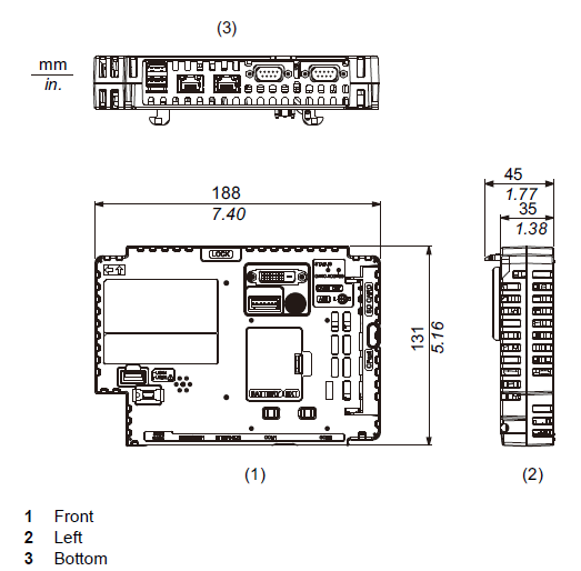
W188 x H131 x D45 mm(W7.4 x H5.16 x D1.77 in.) |
| Panel Cut Dimensions |
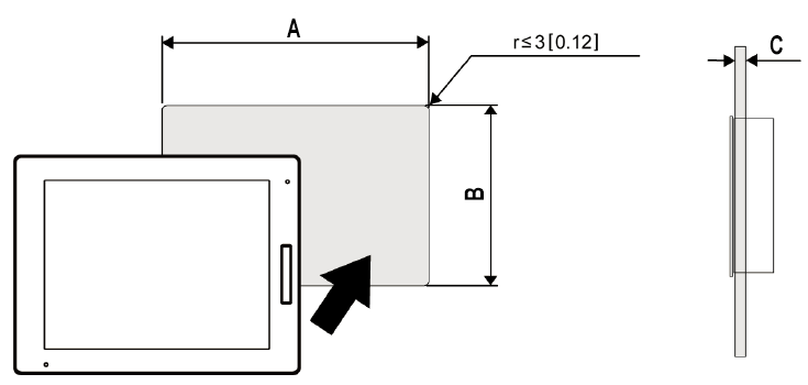
W465 x H319 mm(W18.31 x H12.56 in.) *3 Panel thickness area:1.6...5 mm (0.06...0.2 in.) *4 |
| Weight *5 | 56.8 kg (15.0 lb) or less |
*2 The front face of this product, installed in a solid panel, has been tested using conditions equivalent to the standards shown in the specification.
*3 For dimensional tolerance, everything +1/-0 mm (+0.04/-0 in.) and R in angle are below R3 (R0.12 in.)
*4 Even if the installation wall thickness is within the recommended range for the “Panel Cut Dimensions”, depending on wall’s material, size, and installation location of this product and other devices, the installation wall could warp. To prevent warping, the installation surface may need to be strengthened.
*5 The weight for the combined unit of Box Module and Display Module equals the sum of the weight for the Modules.
External Dimensions
| SP-5800WC |
 |
| SP-5B41 |
 |
Panel Cut-out


